Characteristics of circuit breakers for power supply. Basic technical characteristics of circuit breakers. Types and design features
The installation of protective equipment is an important step in the construction of electrical networks. In the event of large currents, heating occurs, causing the insulation layer of the conductor to melt. This situation leads to a fire. A sharp increase in the current value is associated with a short circuit that occurs during the operation of faulty equipment.
To avoid the threat of fire and damage to the wires, various types of electrical machines are used, depending on the parameters used in conjunction with electrical devices.
Principle of operation and varieties
The principle of operation of electrical switches is to break the electrical circuit when a short circuit occurs. Or exceeding the permissible power for which the electrical network is designed. Electrical circuit breakers are always located at the beginning of the protected section of the circuit. In this case, the type of connected load does not matter.
By their appearance and parametric values, the automata are divided:
- by the number of poles;
- by time-current characteristic;
- by rated current.
 It is also necessary to note the class of current limitation. This value is characterized by the speed of the device reaction to the occurrence of an emergency situation. The division takes place into three classes. For domestic use, the third class is used.
Regardless of their characteristics, the principle of operation is identical for all switches. To connect the machine to the electrical network, set the control switch to the "on" position. The current flowing to the switch is supplied through the input terminal to the solenoid coil, and from it to the bimetallic plate. The plate is a strip of two pressed metals with different coefficients of thermal linear expansion. The current from the plate comes to the output terminal and then enters the electrical circuit. The plate and solenoid are called releases.
Current release - an important structural element, it can be:
- electromagnetic (solenoid);
- thermal (bimetallic plate);
- combined (combination of thermal and electromagnetic);
- independent (by remotely acting on the switch, it turns it off).
 There are two conditions under which the circuit breaker will trip to open the line: overload mode and short circuit mode.
The principle of operation in overload mode is based on the ability of a bimetallic plate to bend under the influence of heat. With an increase in the power per line, the current flowing through the electric machine increases, exceeding the working value switch. As a result, the release heats up, its plate bends and the contact breaks. Accordingly, the electrical circuit is also broken. The supply of current is interrupted. The magnitude of the current at which the plate breaks the contact is adjusted at the factory with the adjustment screw. After the plate has cooled, it returns to its previous shape, and the contact reappears.
In short-circuit mode, the current rises very quickly, the magnetic field generated by it in the solenoid drives the core. The core acts on the release and the electrical circuit breaks, causing an arc. The appearance of an arc negatively affects the internal parts of the machine, therefore, a device for extinguishing it is used. The arc chute is made of plates located parallel to each other, passing through which the arc dissipates.
Thus, the main structural parts can be noted:
- current terminals;
- release:
- control lever;
- release adjusting screw;
- arc suppression chamber.
Number of poles
 The number of poles indicates how many wires can be passed through the breaker at the same time. There are devices with the number of pins from one to four. The device of a single-pole switch is no different from a multi-pole, only in the second case, when the passage of electric current several chains break at the same time.
Single-pole devices are more often used in domestic conditions and are placed in the break of the phase wire, the zero is connected directly through the block, as an introductory machine, its use is not recommended. For installation at the input, two-pole circuit breakers are used, phase and neutral wires are simultaneously connected to them. For use in a three-phase network, a three-pole machine is already used as an input. To protect a four-phase power grid, for example, a star-connected motor, a four-phase automatic is used. In this case, three phase and one neutral wire are connected.
The usual scheme of building protection on electrical switches comes down to installing an input automatic machine of the required number of poles. After it, single-pole ones are installed - one for each group. In this case, the value of the rated current of a single-pole machine is calculated based on the parameters of the group to which it is connected. Its value is chosen less than the input.
Time-current characteristic
 This parameter indicates the ratio of the actual strength of the current passed through the machine to the nominal value. Depending on the value of the ratio, the sensitivity of the machine is determined, which is characterized by the number of false positives. There are different types of machines. They are marked with letters of the Latin alphabet. The most widespread are switches marked B, C and D.
Automatic circuit breakers with characteristic B are switched off within 5-20 seconds. In this case, the current value can exceed the nominal value by five times. These models are widely used in household premises. C marking means shutdown interval 1-10 seconds, while the load is ten times the value. Class D circuit breakers are used to protect motors. The operating current exceeds the rated one by 14–20 times.
Rated current
Indicates the strength of the current that can pass through the electrical machine without triggering. They are available in strictly defined values \u200b\u200bfrom 1 to 63 amperes. There are 12 values \u200b\u200bin total: 1A, 2A, 3A, 6A, 10A, 16A, 20A, 25A, 32A, 40A, 50A, 63A.
The choice of the rated current depends on the power value that the wiring can withstand without damage. This value is determined by the cross-section of the wire and the material of its manufacture. In homes, the most popular machines for use are 6A, 10A and 16A. Automatic devices with a nominal value of 20A, 25A, 32A are used in apartments as introductory, i.e. two-pole.
Location and placement
 The placement method (whether it is an electric single-phase machine or another type) is strictly vertical. The fixed part of the control lever must be on top, that is, the device is switched on by switching from bottom to top. The devices are placed in accessible places, and the possibility of their mechanical damage is excluded.
The most popular is the DIN rail mount. Typically, this rail is installed in the shield. Electrical switches structurally have special grooves into which the rail is inserted.
What are the machines, how they are labeled - you need to know this information in order to choose the right device. Regardless of the manufacturer and type of electrical machines, they are always marked on the front. The marking is carried out according to a single scheme. It includes an indication of all the main parameters:

On the control lever, inscriptions are made indicating the installed position - "on." and "off" or "1" and "0".
Leading brands and manufacturers
The following brands are the leaders in the production of circuit breakers:

These are well-known brands that produce any kind of electrical machines. They are distinguished by their high quality housing, long service life and high mechanical strength. Often, protective covers are additionally installed on them. These manufacturers produce their devices from solid materials. Their quality is confirmed by certificates and the warranty period given by manufacturers for their products.
The main difference between these switching devices from all other similar devices is the complex combination of capabilities:
1. to maintain the rated load in the system for a long time due to the reliable transmission of powerful flows of electricity through its contacts;
2. Protect operating equipment from accidental electrical faults by quickly removing power from it.
Under normal operating conditions, the operator can manually switch loads with circuit breakers, providing:
different power schemes;
changing the network configuration;
withdrawal of equipment from work.
Emergency situations in electrical systems occur instantly and spontaneously. A person is not able to quickly respond to their appearance and take measures to eliminate them. This function is assigned to automatic devices built into the switch.
In the power industry, the division of electrical systems by type of current is accepted:
constant;
alternating sinusoidal.
In addition, there is a classification of equipment according to the voltage value for:
low voltage - less than a thousand volts;
high voltage - everything else.
For all types of these systems, their own circuit breakers are created, designed for repeated operation.

AC circuits
According to the power of the transmitted electricity, automatic switches in alternating current circuits are conventionally divided into:
1.modular;
2. in a molded case;
3. power air.
Modular designs
The specific design in the form of small standard modules with a width of multiples of 17.5 mm determines their name and design with the possibility of mounting on a Din-rail.
The internal structure of one of these circuit breakers is shown in the picture. Its body is completely made of durable dielectric material, excluding.

The supply and outgoing wires are connected to the upper and lower terminal clamp, respectively. A lever with two fixed positions is installed for manual control of the state of the switch:
the upper one is designed to supply current through a closed power contact;
bottom - provides a break in the power supply circuit.
Each of these machines is designed for long-term operation at a certain value (In). If the load becomes larger, then the power contact breaks. For this, two types of protections are placed inside the case:
1. thermal release;
2.current cutoff.
The principle of their operation makes it possible to explain the time-current characteristic, which expresses the dependence of the protection operation time on the load current or failure passing through it.
The graph shown in the picture is for one specific circuit breaker, when the cut-off operating zone is selected at 5 ÷ 10 times the rated current.

At the initial overload, a thermal release is operated, made of which, with an increased current, gradually heats up, bends and acts on the disconnecting mechanism not immediately, but with a certain time delay.
In this way, it allows small overloads associated with short-term connection of consumers to self-eliminate and eliminate unnecessary disconnections. If the load provides critical heating of the wiring and insulation, then the power contact breaks.
When an emergency current arises in the protected circuit, which can burn equipment with its energy, then an electromagnetic coil comes into operation. With an impulse, due to the surge of the load that has arisen, it throws the core onto the disconnecting mechanism in order to instantly stop the out-of-limit mode.
The graph shows that the higher the short-circuit currents, the faster they are disconnected by the electromagnetic release.
The household automatic steam fuse works according to the same principles.
When large currents are broken, an electric arc is created, the energy of which can burn out the contacts. To exclude its effect, an arc-extinguishing chamber is used in circuit breakers, which divides the arc discharge into small flows and extinguishes them due to cooling.
Multiplicity of cutoffs of modular structures
Electromagnetic releases are tuned and matched to work with certain loads because they create different transients when they start. For example, during the switching on of various luminaires, the short-term inrush current due to the changing resistance of the filament can approach three krats of the nominal value.
Therefore, for the socket group of apartments and lighting circuits, it is customary to choose automatic switches with a time-current characteristic of the "B" type. It is 3 ÷ 5 In.
Asynchronous motors, when the rotor is spinning with a drive, cause higher overload currents. For them, select machines with the characteristic "C", or - 5 ÷ 10 In. Due to the created margin in time and current, they allow the engine to spin up and it is guaranteed to enter the operating mode without unnecessary shutdowns.
In industrial production on machine tools and mechanisms there are loaded drives connected to motors, which create more increased overloads. For such purposes, automatic switches of characteristic "D" with a rating of 10 ÷ 20 In are used. They have proven themselves well when working in circuits with active-inductive loads.
In addition, the machines have three more types of standard time-current characteristics, which are used for special purposes:
1. "A" - for long lines with an active load or protection of semiconductor devices with a value of 2 ÷ 3 In;
2. "K" - for pronounced inductive loads;
3. "Z" - for electronic devices.
In the technical documentation from different manufacturers, the cutoff rate for the last two types may slightly differ.
This class of devices is capable of switching higher currents than modular designs. Their load can reach up to 3.2 kiloamperes.

They are manufactured according to the same principles as modular structures, but taking into account the increased requirements for the transmission of the increased load, they are trying to give them relatively small dimensions and high technical quality.
These machines are designed for safe operation in industrial facilities. By the value of the rated current, they are conventionally divided into three groups with the ability to switch loads up to 250, 1000 and 3200 amperes.
Constructive design of their case: three- or four-pole models.
Power air switches
They operate in industrial installations and handle very heavy currents up to 6.3 kiloamperes.

These are the most complex devices for switching devices of low-voltage equipment. They are used for the operation and protection of electrical systems as input and output devices for high power distribution systems and for connecting generators, transformers, capacitors or powerful electric motors.
A schematic representation of their internal structure is shown in the picture.

Here, a double break of the power contact is already used and arc extinguishing chambers are installed with gratings on each side of the disconnection.
The operation algorithm involves the closing coil, the closing spring, the motor-drive for the spring charging and the automation elements. A current transformer with a protective and measuring winding is built in to monitor the flowing loads.
Circuit breakers for high-voltage equipment are very complex technical devices and are made strictly individually for each voltage class. They are usually used.
Requirements are imposed on them:
high reliability;
security;
performance;
ease of use;
relative noiselessness during operation;
optimal cost.
Loads that break during an emergency trip are accompanied by a very strong arc. Various methods are used to extinguish it, including breaking the circuit in a special environment.
This switch includes:
contact system;
arc extinguishing device;
live parts;
insulated housing;
drive mechanism.
One of these switching devices is shown in the photo.

For high-quality operation of the circuit in such structures, in addition to the operating voltage, take into account:
the rated value of the load current for its reliable transmission in the on state;
maximum short-circuit current at rms value that the tripping mechanism can withstand;
admissible component of the aperiodic current at the moment of circuit break;
automatic reclosing capabilities and two automatic reclosure cycles.
According to the methods of extinguishing the arc during tripping, the switches are classified into:
oil;
vacuum;
air;
sF6 gas;
autogas;
electromagnetic;
auto-pneumatic.
For reliable and convenient operation, they are equipped with a drive mechanism that can use one or several types of energy or their combinations:
cocked spring;
lifted load;
compressed air pressure;
electromagnetic pulse from the solenoid.
Depending on the conditions of use, they can be created with the ability to operate under voltage from one to 750 kilovolts, inclusive. Naturally, they have a different design. dimensions, automatic and remote control capabilities, protection settings for safe operation.
The auxiliary systems of such circuit breakers can have a very complex branched structure and be located on additional panels in special technical buildings.
DC circuits
These networks also have a huge number of circuit breakers with different capabilities.
Electrical equipment up to 1000 volts
Modern modular devices with the ability to mount on a Din-rail are massively introduced here.
They successfully complement the classes of old automatic machines such as, AE and other similar ones, which were fixed on the walls of the panels with screw connections.
DC modular designs have the same design and principle of operation as their AC counterparts. They can be performed by one or several units and are selected according to the load.
Electrical equipment above 1000 volts
High-voltage circuit breakers for direct current are used in electrolysis plants, metallurgical industrial facilities, railway and city electrified transport, and energy enterprises.

The main technical requirements for the operation of such devices correspond to their alternating current counterparts.
Hybrid switch
Scientists from the Swedish-Swiss company ABB succeeded in developing a high-voltage DC circuit breaker that combines two power structures in its device:
1. SF6 gas;
2. vacuum.
It was named hybrid (HVDC) and uses the technology of sequential arc quenching in two environments at once: sulfur hexafluoride and vacuum. For this, the following device is assembled.
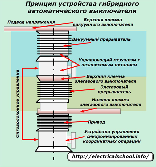
Voltage is applied to the upper busbar of the hybrid vacuum circuit breaker, and it is removed from the lower busbar of the SF6 circuit breaker.
The power parts of both switching devices are connected in series and are controlled by their individual drives. In order for them to work simultaneously, a synchronized coordinate operations control device was created, which transmits commands to the control mechanism with independent power supply via a fiber-optic channel.
Due to the use of high-precision technologies, the designers managed to achieve the coordination of actions of the actuators of both drives, which fits into a time interval of less than one microsecond.
The circuit breaker is controlled from a relay protection unit built into the power line through a repeater.
The hybrid circuit breaker has made it possible to significantly improve the efficiency of composite SF6 and vacuum structures by using their combined characteristics. At the same time, it was possible to realize the advantages over other analogues:
1.the ability to reliably disconnect short-circuit currents at high voltage;
2. the possibility of a small effort to carry out the switching of power elements, which made it possible to significantly reduce the dimensions and. accordingly, the cost of equipment;
3. the availability of meeting various standards for the creation of structures operating as a part of a separate circuit breaker or compact devices at one substation;
4. the ability to eliminate the effects of rapidly increasing recovery stress;
5. Possibility of forming a basic module for working with voltages up to 145 kilovolts and above.
A distinctive feature of the design is the ability to break an electrical circuit in 5 milliseconds, which is almost impossible to perform with power devices of other designs.
The hybrid circuit breaker device was ranked among the top ten developments of the year according to the MIT (Massachusetts Institute of Technology) Technology Review.
Other manufacturers of electrical equipment are engaged in similar research. They also achieved certain results. But ABB is ahead of them in this matter. Its management believes that the transmission of AC power is causing its great losses. They can be significantly reduced by using high voltage direct voltage circuits.
The development of security tools for power grids has become relevant since their inception. Various overloads led not only to damage to cables, but also to the occurrence of fires.
Today, the most popular devices of this type are circuit breakers.
They help prevent events such as fires, damage to electrical wiring. Since they are automatic, the actuation occurs without human intervention. Choosing the right switch will help keep your room safe from accidents.
Design and principle of operation
Understanding the automatic trip mechanism of the circuit breaker will help you select the correct model. Structurally, the machine includes the following key elements:
- terminals;
- toggle switch;
- electromagnetic release;
- bimetallic plate.
 Depending on the type of overload, one of two mechanisms is triggered.
When an overload of the circuit occurs with a current exceeding the rating by several times, the bimetallic plate is triggered. It heats up within a few seconds, resulting in thermal expansion. When a certain size is reached, it is significantly bent and the circuit is opened. The plate parameters are set by the manufacturer. For switches used in everyday life, the response time is 5–20 s. They are usually marked with letters: B, C, D.
The short-circuit (SC) mode is characterized by an avalanche-like increase in current that exceeds not only the rating, but also its maximum permissible load. There is no time left for the plate to heat up during a jump, otherwise the wiring may melt. In such a situation, an electromagnetic release is triggered. The magnetic field drives the core, which opens the circuit. Instant actuation allows you to protect the room from the effects of short circuit.
Classification
Electrical machines differ in the following key characteristics:
- number of poles;
- time current characteristic;
- operating current;
- breaking capacity.
Number of poles
 This characteristic corresponds to the number of wiring lines that can be directly connected to the machine. All output wires will be disconnected simultaneously when the machine is triggered.
Single-pole automatic machine. This is the simplest type of circuit protection device. Only 2 wires are connected to it: one goes to the load, the second is the power supply. It is placed on a standard 18 mm din rail. The power wire is connected from the top, and the load to the bottom terminal. It can operate on single, two or three phase power lines. In addition to the power and load wires, it has a neutral and ground, which are connected to the corresponding bus. Such machines are not installed at the input, since the circuit will open only along the phase line. Zero wiring remains closed and in case of failures, potential may remain on it.
Bipolar machine, its difference from unipolar. This type of circuit breaker allows you to completely de-energize the wiring of the room. It allows you to synchronize the moment when two of its output lines are turned off. The latter leads to a higher level of safety during electrical work. It can be used as a stand-alone toggle switch for appliances such as a water heater or washing machine. The connection is made through 4 cables: a pair at the input and output.
A simple question is logical: is it possible to connect two single-pole machines instead of one two-pole? Of course no. After all, with an automatic trip, the two-terminal disconnects all output lines. For a pair of independent machines, overload may not occur on one of the lines and the de-energization will be partial. In ordinary apartments, you can connect the phase and neutral line to this machine. When opened, a complete de-energization of the entire group of devices that are powered from it will occur.
 Three and four-pole machines. All three or four phase conductors are connected to the poles of the corresponding circuit breaker. They are used when connected by a star, when the phase wires are protected from overloads, and the middle wire remains switched all the time, or a triangle, when there is no middle central cable, and the phase wires are protected.
If overload occurs on one of the lines, shutdown occurs immediately on all the others. These machines are connected to 6 (three-phase machine) or 8 wires. 3-4 at the exit and the same number of lines at the exit. They are mounted on a din rail 54 (three-phase automatic) and 72 mm long, respectively. They are used most often in industrial installations, when connecting powerful electric motors.
Time current parameter
The nature of power consumption by different devices varies even if the power values \u200b\u200bare the same. Uneven consumption dynamics with correct operation, a load surge during switching on - all these phenomena lead to significant changes in such a parameter as consumption current. Power dispersion can lead to a false trip of the circuit breaker.
In order to exclude such situations, dynamic operating parameters are introduced, called time current characteristics of circuit breakers. By this parameter, machines are divided into several types. Each machine has its own response time. The front panel of the switch is marked with the corresponding letter from the list: A, B, C, D, K, Z.

Rated current
The differences between the machines, depending on the rated current values, are divided into several groups (12 current levels). It is directly related to the response time when the power consumption is exceeded. It is possible to determine the operating value purely theoretically by adding the sum of the currents consumed by each of the devices separately. In this case, you should take a small margin. You should also not forget about the possibilities of electrical wiring.
The machines are designed primarily to prevent damage. Depending on the metal of the wires and their cross-section, the maximum load is calculated. The ratings of the current circuit breakers allow for this separation.

Breaking capacity
This parameter depends on the maximum current value in the event of a short circuit, provided that the machine disconnects the network. By the value of short-circuit current, all automata are divided into three groups.
- The first includes devices with a rating of 4.5 kA. They are used in private houses intended for human habitation. The current limit is approximately 5 kA. This is due to the fact that the resistance of the system of conductive cables going to the house from the substation is 0.05 ohms.
- The second group has rated 6 kA. This level is already applied in residential apartment buildings and public places. The maximum current can reach 5.5 kA (wiring resistance 0.04 Ohm). In this case, model types are used: B, C, D.
- In industrial plants the rating is 10 kA. The limit value of the current that can occur in a circuit near a substation has the same value.
How to choose the right machine
 Until recently, porcelain fuses with fusible elements were widely used. They were well suited for the same load of Soviet apartments. Now the number of household appliances has become much more, as a result of which the likelihood of getting a fire with old fuses has increased. To prevent this, it is necessary to carefully approach the choice of a machine with the correct characteristics. Excessive power reserves should be avoided. The final choice is made after a few simple steps.
Determination of the number of poles
When determining this parameter of the switch, one should be guided by a simple rule. If you plan to secure sections of the circuit with devices that have low power consumption (for example, lighting devices), then it is better to leave your choice on a single-pole machine (more often class B or C). If you plan to connect a complex household device with significant power consumption (washing machine, refrigerator), then you should install a two-pole machine (class C, D). If the equipment of a small production workshop or a garage with multiphase propulsion systems is carried out, then the three-pole option (class D) should be chosen.
Calculation of power consumption
As a rule, by the time it is planned to connect the machine, the wiring to the room has already been installed. Based on the cross-section of the conductors and the type of metal (copper or aluminum), you can determine the maximum power. For example, for a copper conductor of 2.5 mm 2, this value is 4-4.5 kW. But wiring is often failed with a large margin. And the calculation should be done before the start of all installation work.
 In this case, a value is required about how much total power will be used by all devices. It is always possible to turn them on at the same time. So, in an ordinary kitchen, such devices are often used:
- refrigerator - 500 watts;
- electric kettle - 1700 W;
- microwave - 1800 W
The total load is 4 kW and an automatic machine with 25 A is enough for it. But there are always consumers who turn on occasionally and can create factors that contribute to the operation of the circuit breaker. Such devices may be a combine or mixer. Therefore, you should take the machine with a margin of 500-1200 watts.
Calculating the rated current
Since the power in single-phase networks is equal to the product of voltage and current, then the current can be easily determined as a quotient of power and voltage. For the above example, this value is easy to calculate, knowing that the voltage in the network is 220 V. The current consumption is 18.8 A. Given a margin of 500–1200 V, it will be 20.4–23.6 A.
In order that the work does not stop even with such short-term excess of the load, the rated current for the machine can be taken equal to 25 A. Approximately the same value corresponds to the rating, based on a copper cable with a cross section of 2.5 mm 2, which is enough with a margin for such load. A circuit breaker with a rated current of 25 A will trip before it starts to heat up.
Determination of the current characteristic time
 This parameter is determined by a special table, which lists the inrush currents and their flow time. For example, for a domestic refrigerator, the inrush current multiplicity is 5. At a power of 500 W, the operating current is 2.2 A. The inrush current will be 2.2 * 7 \u003d 15.4 A. Frequency data is also taken from a special table.
Table No. 1. Starting currents and pulse durations for household appliances
For the selected device, this characteristic does not exceed 3 s. The choice becomes obvious: for such a consumer it is necessary to take a type B circuit breaker. It is permissible to make a choice of an automaton according to the load power. You can skip the last step by opting for a class B circuit breaker. For domestic needs, the characteristics of class B and C electrical switches are often sufficient.
In practical applications, it is important not only to know the characteristics of the circuit breakers, but also to understand what they mean. Thanks to this approach, you can decide on most technical issues. Let's look at what is meant by certain parameters indicated on the labeling.
Abbreviation used.
Device marking contains all the necessary information describing the main characteristics of circuit breakers (hereinafter referred to as AB). What they mean will be discussed below.
Time-current characteristic (VTX)
With the help of such a graphical display, you can get a visual representation under what conditions the circuit power disconnection mechanism will be activated (see Fig. 2). The graph shows the time required to activate AB as a vertical bar. The horizontal scale shows the I / In ratio.
Fig. 2. Graphical display of the current characteristics of the most common types of machinesThe permissible excess of the rated current determines the type of time-current characteristics for releases in devices that perform automatic shutdown. In accordance with the current standard (GOST P 50345-99), each species is assigned a specific designation (from Latin letters). The permissible excess is determined by the coefficient k \u003d I / In, for each type the values \u200b\u200bestablished by the standard are provided (see Fig. 3):
- “A” - maximum - three-fold excess;
- "B" - from 3 to 5;
- "C" - 5-10 times more than the standard;
- "D" - 10-20 times excess;
- “K” - from 8 to 14;
- "Z" - 2-4 more than the regular one.
 Figure 3. Basic activation parameters for various types
 Note that this graph fully describes the conditions for activating the solenoid and thermoelement (see Fig. 4).

Considering all of the above, it can be summarized that the main protective characteristic of AB is due to the time-current dependence.
A list of typical time-current characteristics.
Having decided on the marking, we turn to the consideration of various types of devices that meet a certain class, depending on the characteristics.

Characteristic type "A"
Thermal protection AB in this category is activated when the ratio of circuit current to rated (I / I n) exceeds 1.3. Under these conditions, shutdown will occur after 60 minutes. As the rated current is further exceeded, the tripping time is reduced. Activation of electromagnetic protection occurs when the nominal value is twice exceeded, the response speed is 0.05 sec.
This type is installed in circuits not subject to short-term overload. An example is the circuitry on semiconductor elements, in the event of failure of which, the excess current is negligible. In everyday life, this type is not used.
Characteristic "B"
The difference between this type and the previous one is in the operating current, it can exceed the regular one from three to five times. In this case, the solenoid mechanism is guaranteed to be activated at five times the load (de-energizing time - 0.015 sec.), Thermoelement - three times (shutdown will take no more than 4-5 sec.).
These types of devices have found application in networks for which high inrush currents are not characteristic, for example, lighting circuits.

Characteristic "C"
This is the most common type, its overload capacity is higher than the previous two types. When the normal mode is exceeded fivefold, the thermoelement is triggered, this is a circuit that cuts off the power supply for one and a half seconds. The solenoid mechanism is activated when the overload exceeds the norm ten times.
The AB data is designed to protect the electrical circuit, in which a moderate inrush current may occur, which is typical for a household network, which is characterized by a mixed load. When buying a device for the home, it is recommended to opt for this type.
 Three-pole automatic machine Legrand
 Characteristic "D"
This type of AB is characterized by high overload characteristics. Namely, a ten-fold excess of the norm for a thermocouple and a twenty-fold excess for the solenoid.
Such devices are used in circuits with large starting currents. For example, to protect the starting devices of induction motors. Figure 9 shows two devices in this group (a and b).
 Figure 9. a) BA51-35; b) BA57-35; c) BA88-35
 Characteristic "K"
In such AVs, activation of the solenoid mechanism is possible when the current load is 8 times exceeded, and it is guaranteed to occur when there is a twelve-fold overload of the normal mode (eighteen-fold for constant voltage). Load disconnection time no more than 0.02 sec. As for the thermoelement, its activation is possible when 1.05 of the normal mode is exceeded.
Scope of application - circuits with inductive load.
Characteristic "Z"
This type is characterized by a small permissible excess of the rated current, the minimum boundary is two times the standard, and the maximum is four times. The thermoelement response parameters are the same as those of AB with characteristic K.
This subspecies is used to connect electronic devices.
Characteristic "MA"
A distinctive feature of this group is that the thermocouple is not used to disconnect the load. That is, the device protects only against short-circuit, this is quite enough to connect an electric motor. Figure 9 shows such a device (c).
Normal operation current
This parameter describes the maximum permissible value for the normal operating mode, when it is exceeded, the load shedding system will be activated. Figure 1 shows where this value is displayed (IEK products are taken as an example).

Thermal parameters
This term refers to the conditions of operation of the thermocouple. This data can be obtained from the corresponding time-current graph.
Ultimate breaking capacity (PKS).
This term denotes the maximum allowable load value at which the device can open the circuit without losing functionality. In Figure 5, this marking is indicated by a red oval.
 Fig. 5. The device of the company Schneider Electric
 Current limitation categories
This term is used to describe the AB's ability to trip the circuit before the short-circuit current in it becomes maximum. The devices are produced with current limitation of three categories, depending on the load disconnection time:
- 10 ms and more;
- from 6 to 10 ms;
- 2.5-6 ms.

Note that ABs belonging to the first category may not have the corresponding marking.
A small life hack on how to choose the right switch for your home

The fire-hazardous consequences of destruction are easier and cheaper to prevent than to bitterly complain about measures not taken. Prevention of a fire in the electrical network consists in the installation of protective equipment. In the last century, the function of protection against short circuits and against the danger of overload was entrusted to porcelain fuses with replaceable fuses, then to automatic plugs. However, due to a significant increase in the load on power lines, the situation has changed. It's time to replace outdated devices with reliable machines. In order for the selection of a circuit breaker to end with the purchase of a device with the proper characteristics, information is needed about a number of electrical nuances.
Why do we need machines?
Circuit breakers - devices designed to protect the power cable, more precisely, its isolation from reflow and integrity. The machines do not protect the owners of the equipment from blows and do not protect the equipment itself. For these purposes, they are equipped with an RCD. The task of automatic machines is to prevent overheating that accompanies the flow of overcurrents to the entrusted section of the circuit. Thanks to their use, the insulation will not be melted and damaged, which means that the wiring will operate in normal mode without fire risks.

The work of automatic switches is to open the electrical circuit in the event of:
- occurrence of TKZ (hereinafter short-circuit currents);
- overload, i.e. passing currents on the protected area of \u200b\u200bthe network, the strength of which exceeds the permissible operational value, but is not TKZ;
- a tangible decrease or complete disappearance of voltage.
The machines are guarding the next section of the chain. Simply put, are set on input. They protect the lines of lighting and sockets, the mains for connecting household equipment and electric motors in private houses. These lines are laid with cables of different cross-sections, because they are powered by equipment of different power. Therefore, to protect network sections with unequal parameters, protection devices with unequal capabilities are needed.
If you want to learn how to install a socket, we recommend that you read the article
It would seem that you can get the most powerful automatic shutdown devices for installation on each of the lines without unnecessary trouble. The step is fundamentally wrong! And its result will lay a direct "path" to the fire. Protection against electric current quirks is a delicate matter. Therefore, it is better to learn how to choose a circuit breaker, and install a device that breaks the circuit when there is a real need for it.
Attention. An oversized circuit breaker will pass critical currents for wiring. It will not promptly disconnect the protected section of the circuit, due to which the cable insulation will melt or burn.
Automata with lowered characteristics will also bring a lot of surprises. They will endlessly break the line at the start of the equipment and eventually break down due to repeated exposure to too high currents. Contacts are soldered, which is called "stuck".
Design and principle of operation of the machine
It will be difficult to make a choice without understanding the circuit breaker device. Let's see what is hidden in a tiny box of refractory dielectric plastic.

Release devices: their types and purpose
The main working bodies of the circuit breakers are releases that open the circuit in case of exceeding the standard operating parameters. Releases differ in the specificity of their action and in the range of currents to which they are required to react. Their ranks include:
- electromagnetic releases, almost instantly reacting to the occurrence of TKZ and "cutting off" the protected section of the network in hundredths or thousandths of a second. They consist of a coil with a spring and a core, which is drawn in by the action of overcurrents. Retracting, the core strains the spring, and it makes the release device work;
- thermal bimetallic releasesacting as a barrier against overloads. They undoubtedly also react to TKZ, but they are obliged to perform a slightly different function. The task of thermal brothers is to break the network if currents pass through it that exceed the maximum operating parameters of the cable. For example, if a current of 35A flows through the wiring intended to transport 16A, the plate consisting of two metals will bend and cause the machine to shut down. Moreover, she will courageously "hold" 19A for more than an hour. But 23A will not be able to “endure” the whole hour, it will work earlier;
- semiconductor releases they are rarely used in household machines. However, they can serve as a working body of a protective switch at the entrance to a private house or on the line of a powerful electric motor. Measurement and fixing of the anomalous current in them is carried out by transformers, if the device is installed on an alternating current network, or choke amplifiers, if the device is connected to a direct current line. The decoupling is performed by the solid-state relay block.
There are also zero or minimum releases, most often used as a supplement. They disconnect the network when the voltage drops to any limit value specified in the data sheet. A good option are remote releases that allow you to turn off and on the machine without opening the control cabinet, and locks that fix the "off" position. It is worth considering that equipping these useful additions significantly affects the price of the device.


Automatic machines used in everyday life are most often equipped with a harmoniously working combination of electromagnetic and thermal releases. Devices with one of these devices are much less common and used. All the same, combined type circuit breakers are more practical: two in one are more profitable in every sense.
Critical additions
There are no useless components in the circuit breaker design. All components work diligently in the name of a common preventive business, these are:
- an arcing device mounted on each pole of the machine, of which there are from one to four pieces. It is a chamber in which, by definition, an electric arc is extinguished, which occurs when the power contacts are forced to open. Copper-plated steel plates are arranged in parallel in the chamber, dividing the arc into small parts. The fragmented threat to the fusible parts of the machine in the arc extinguishing system cools down and disappears completely. Combustion products are discharged through the gas outlet channels. The addition is a spark arrester;
- a system of contacts, subdivided into fixed, mounted in the case, and movable, pivotally attached to the semi-axles of the release mechanism levers;
- calibration screw, with the help of which the thermal release is adjusted at the factory;
- mechanism with the traditional inscription "on / off" with the corresponding function and with a handle intended for implementation;
- connection terminals and other devices for connection and installation.
This is how the arc extinguishing process looks like:

Let's dwell a little on power contacts. The fixed version is soldered with electromechanical silver, which optimizes the electrical durability of the switch. When a cheap silver alloy is used by an unscrupulous manufacturer, the weight of the product is reduced. Sometimes silver-plated brass is used. "Substitutes" are lighter than a standard metal, therefore a high-quality device of a reputable brand weighs slightly more than a "left" analogue. It is important to note that when replacing silver soldering of fixed contacts with cheap alloys, the resource of the machine is reduced. It will withstand less cycles of switching off and then switching on.
Let's decide on the number of poles
It has already been mentioned that the poles of this protection device can be from 1 to 4 pcs. It is as easy as shelling pears to choose the number of poles of the machine. it all depends on its purpose of use:
- a single-pole circuit breaker will perfectly cope with the protection of lighting lines and sockets. Only mounted on the phase, no zeros !;
- a two-pole switch will protect the cable supplying electric stoves, washing machines and water heaters. If there is no powerful household appliances in the house, it is placed on the line from the dashboard to entering the apartment;
- a three-pole device is required for three-phase wiring equipment. This is already a semi-industrial scale. In everyday life, there may be a line of a workshop or a borehole pump. A three-pole device must not be connected to an earth conductor. He must always be on full alert;
- four-pole circuit breakers are used to protect against the fire of four-wire wiring.
If it is planned to protect the wiring of an apartment, bathhouse, house with two-pole and single-pole circuit breakers, first a two-pole device is installed, then a single-pole one with a maximum rating, then in descending order. The "ranking" principle: from a more powerful component to a weak, but sensitive one.

Marking - food for thought
We figured out the device and the principle of operation of the machines. Learned what for. Now we can safely proceed to the analysis of the markings affixed to each circuit breaker, regardless of the logo and country of origin.

The main reference is the face value.
Because the purpose of purchasing and installing the machine is to protect the wiring, then first of all you need to focus on its characteristics. The current flowing through the wires heats the cable in proportion to the resistance of its current-carrying conductor. In short, the thicker the core, the greater the value of the current can pass through it without melting the insulation.
In accordance with the maximum value of the current transported by the cable, the rating of the automatic shutdown device is selected. You don't need to calculate anything, the interdependent values \u200b\u200bof wiring devices and wiring by caring electricians have long been summarized in the table:

The tabular information should be slightly adjusted according to domestic realities. The predominant number of household outlets is designed to connect a wire with a wire of 2.5 mm², which suggests, according to the table, the possibility of installing an automatic machine with a rating of 25A. The actual rating of the outlet itself is only 16A, which means you need to buy a circuit breaker with a rating equal to the outlet rating.
A similar adjustment should be made if there is any doubt about the quality of the existing wiring. If there are suspicions that the cable cross-section could not correspond to the size indicated by the manufacturer, it is better to play it safe and take an automatic machine whose rating is one position less than the table indicator. For example: according to the table, an automatic machine for 18A is suitable for cable protection, and we take it for 16A, because we bought the wire from Vasya in the market.
Calibrated Characteristic Rating
This characteristic is the operating parameters of the thermal release or its semiconductor analogue. It is a coefficient multiplied by which we get the overload current that the device can hold or not hold for a certain period of time. The value of the calibrated characteristic is established during the production process, it cannot be adjusted at home. Pick it up from the standard range.
The calibrated characteristic indicates how long and how much overload the machine can withstand without disconnecting the circuit section from the power supply. Usually these are two numbers:
- the smallest value tells that the machine will pass current with parameters exceeding the standard for more than an hour. For example: a 25A circuit breaker will pass a current of 33A for more than an hour without disconnecting the protected section of wiring;
- the highest value is the limit beyond which shutdown will occur in less than an hour. The device indicated in the example will quickly turn off at a current of 37 or more Amperes.
If the wiring runs in a groove formed in a wall with impressive insulation, the cable will practically not be cooled during overload and the accompanying overheating. So, in an hour the wiring can be pretty bad. Maybe no one will notice the result of the excess right away, but the service life of the wires will be significantly reduced. Therefore, for hidden wiring, we will look for a switch with minimum calibration characteristics. For the open variant, you don't need to dwell on this value.

Setpoint - indicator of instantaneous operation
This figure on the case is a characteristic of the operation of the electromagnetic release. It denotes the limit value of the abnormal current strength, which, with repeated shutdowns, will not affect the performance of the device. It is normalized in current units, and indicated by numbers or Latin letters. With numbers, everything is extremely simple: this is the face value. But the hidden meaning of the letter designations is worth finding out.
Letters are affixed to machines made according to DIN standards. They denote the multiplicity of the maximum current that occurs when the equipment is turned on. A current that is several times higher than the operating characteristics of the circuit, but does not cause a shutdown and does not make the device unusable. It is simpler how many times the switching current of the equipment can exceed the rating of the device and cable without threatening consequences.
For domestic circuit breakers, these are:
- IN - designation of machines capable of reacting without their own damage to currents exceeding the nominal value in the range from 3x to 5 times. They are very suitable for equipping old buildings and countryside. They are not often used, therefore for the distribution network they are most often a custom-made item;
- FROM - designation of these protective equipment, the response range of which is in the range from 5 to 10 times. The most common option, in demand in new buildings and in new country houses with autonomous communications;
- D - designation of switches that instantly break the network when a current arrives with a force exceeding the rating from 10 to 14, sometimes up to 20 times. Devices with such characteristics are only needed to protect the wiring of powerful electric motors.
Abroad there are variations, both upward and downward, but they should not be of interest to the average owner of domestic property.
Current limit class and its meaning
This is briefly about this, because most of the devices offered by the trade belong to the 3rd class of current limitation. Occasionally found 2nd. This is an indicator of the speed of the apparatus. The higher it is, the faster the device will respond to TKZ.
There is a lot of information, but without it it will be difficult to choose the right circuit breaker and protect property from unwanted fires. Information is also needed for those who will order the installation of protection devices. After all, not every electrician who positions himself as a great specialist should be unconditionally trusted.


